EN
EN
 AR
AR
 BG
BG
 HR
HR
 CS
CS
 DA
DA
 NL
NL
 FI
FI
 FR
FR
 DE
DE
 EL
EL
 HI
HI
 IT
IT
 JA
JA
 KO
KO
 NO
NO
 PL
PL
 PT
PT
 RO
RO
 RU
RU
 ES
ES
 SV
SV
 CA
CA
 TL
TL
 IW
IW
 ID
ID
 LV
LV
 LT
LT
 SR
SR
 SK
SK
 UK
UK
 VI
VI
 SQ
SQ
 HU
HU
 TH
TH
 TR
TR
 FA
FA
 MS
MS
 GA
GA
 LA
LA

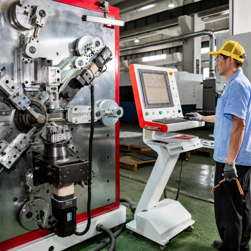
Design for Manufacturing is the best approach for cost reduction and quality improvement. Small changes in the design can result in reduction of fabrication costs and lead time of copper busbars in electric vehicle battery systems, power distribution and renewable energy applications. Over-specification is a common problem among many engineers who overspecify features increase the machining complexity with no functional value. You can gain insight into your design choices and constraints to produce a design with the same electrical and mechanical characteristics at lower cost. Many customers have approached Kinto for copper busbar design optimization for High accuracy and tight tolerance parts manufacturing. This guide provides valuable guidance on DFM principles that don't cost money but keep products reliable.
Simplify Hole Patterns and Spacing
Hole drilling is one of the most popular processes in the manufacturing of copper busbar, and each hole increases the cost of the process. Tooling time, tool wear and inspection are needed for each hole. Save costs: The number of mounting or connection points should be limited to the required amount only. Also, don't get a bunch of tiny holes that will need several changes or special drill bits in the process. Provide adequate spacing between holes and from edge of the busbar. Copper is somewhat soft in nature and making holes too near to the edge can cause deformation or tearing during punching or drilling. As a general rule, holes should be located at least 1.5 time the material thickness from edge, and the spacing between holes should be no less than the material thickness. If the busbar is to be plated, then the question is – are you required to have all openings entirely filled or is partial plating sufficient for your use? All these little tweaks add up to big cycle times savings.
Optimize Bend Radii for Copper‘s Characteristics
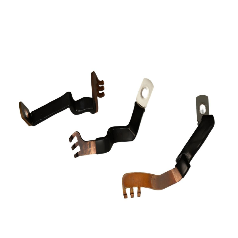
Copper behaves differently from steel when bent, and its response varies significantly with alloy and temper. If the bend radius is too small for the alloy and temper you desire, it may result in cracking, surface defects or require additional annealing steps that may be time consuming and costly. Optimum bend radius for the inside of the bends for most copper busbar applications is one to two times the size of the material itself. For softer tempers (annealed copper) tight radii are obtained but when used for vibrating applications, the mechanical strength may be inadequate. Tempers used during the manufacturing process that make the harder temper, will not bend easily and may need broader radii. Coordinating with the fabricator early in the process to select the right temper that balances electrical conductivity, mechanical strength, and formability. Take the bend direction with respect to the direction of the copper sheet rolling direction into account as well. Bending copper across the rolling direction (rather than with it) reduces the risk of surface fracturing. While a wide range of unique geometries can be created with Kinto's precision machines, those that "play the game" of natural copper-forming will always be less costly.
Reduce Secondary Operations Through Smart Design
Secondary operations like deburring, plating masking, more passes are a significant cost driver. If these steps are reduced or eliminated, then a well designed busbar will do the job. Do not call for non standard thicknesses that need to be custom rolled or have too much surface grinding. Avoid masking in desired wall sections due to the presence of automatic traps in plating solution or manual masking. If flexible busbar connections are required, it may be better to install laminated shunts into the main busbar body, instead of complex flexible jumpers which need to be welded into place or bolted onto the body of the busbar. Design flat uninterrupted surfaces to be easily covered with tape, powder coating or heat shrink for insulation requirements. Narrow channels, difficult to reach areas due to sharp corners, need hand finishing. Rounded corners and generous radii help to reduce stress concentration, and also enable automated finishing processes.
Tolerance Strategy That Balances Precision and Cost
A tighter tolerance will always cost more to produce. It is not a linear increase – reducing tolerance from 0.10 to 0.05 can cause Machining/Inspection to increase more than 2x. Do not specify tighter than necessary. Do not put tolerance in a dimension if it will not impact form or function of the part. Some parts, like busbars of many units that may compensate by deflection when installed, may not need extreme positional accuracy on its length and width. Establish dimensioning & tolerancing that allows use of Geometric Dimensioning and Tolerancing (GD&T)symbols and apply tolerance to critical features that truly need it – like locations of mounting holes and dimensions relating to mounting interfaces, for example. This does not give fabricator false idea that all features are needing highest accuracy. Kinto’s fabrication capabilities are very high precision. In order to produce custom geometries to our capabilities we will encourage our customer to apply tight tolerances only to where necessary purely to function. The saving of producing with looser tolerances can be invested into other material types, higher-end components, or increased prototyping efforts. Utilizing this Design for Manufacturing methodology during the initial design stages will help you save on your overall costs and have cost effective solutions.