EN
EN
 AR
AR
 BG
BG
 HR
HR
 CS
CS
 DA
DA
 NL
NL
 FI
FI
 FR
FR
 DE
DE
 EL
EL
 HI
HI
 IT
IT
 JA
JA
 KO
KO
 NO
NO
 PL
PL
 PT
PT
 RO
RO
 RU
RU
 ES
ES
 SV
SV
 CA
CA
 TL
TL
 IW
IW
 ID
ID
 LV
LV
 LT
LT
 SR
SR
 SK
SK
 UK
UK
 VI
VI
 SQ
SQ
 HU
HU
 TH
TH
 TR
TR
 FA
FA
 MS
MS
 GA
GA
 LA
LA

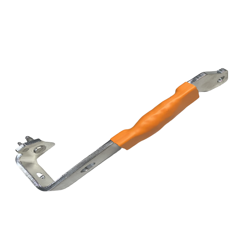
Selecting the correct busbar size begins with accurately calculating its current carrying capacity. If the busbar is undersized, it will overheat, incur energy losses, and could ultimately lead to system failure. An oversized busbar is equally undesirable, as it wastes material, adds unnecessary weight, and increases production costs. Several factors come into play when determining the optimal size for a copper or aluminum busbar to safely carry a given current. This guide summarizes four key factors in busbar current rating calculation and practical provides guidance for making precise and reliable engineering decisions.
Understand the Relationship Between Cross Section and Current Rating
The cross sectional area of the busbar is the most fundamental parameter to determine the current carrying capacity. A larger cross section allows more current to flow, due to the increase number of electron paths and greater surface area for heat dissipation. However, the relationship between cross-sectional area and current rating is not linear. Doubling the cross-section does not double the current rating, because heat generation is proportional to the square of the current(I²R losses). In practice, engineers often consult standard ampacity tables that provide reference current ratings for commonly used bars. For example, under typical free-air conditions, a small copper busbar with a cross-sectional area of around 10 mm² may carry tens of amperes, while a 100 mm² copper busbar can often carry several hundred amperes. However, the exact current rating depends not only on cross-sectional area, but also on the busbar dimensions, ambient temperature, allowable temperature rise, installation method, spacing, and cooling conditions. The conductivity of aluminum is approximately 60 percent of that of copper, and so the cross section of the aluminum conductor that conveys the same current is larger. For custom busbars, Kinto collaborates with its clients to determine the optimal cross section that meets electrical performance requirements while considering space and weight constraints.
Account for Temperature Rise and Ambient Conditions
The current-carrying capacity is not a fixed value. It varies with the maximum allowable temperature rise of the busbar and the ambient temperature around the busbar. Each busbar has resistance losses that result in heat generation. This heat should be dissipated to the surroundings without exceeding the insulation rating or creating safety hazards. The typical design temperature rise is 30–65 °C above ambient. If the ambient temperature inside an enclosure is already 50 °C, the current rating must be significantly derated. Higher ambient temperatures generally reduce the allowable current carrying capacity, while improved cooling conditions can significantly increase it. On the other hand, the capacity can be increased if the cooling is improved by means of forced air or direct heat sinking. At the design stage, Kinto recommends customers set the busbar's expected operating environment and maximum allowable temperature to ensure the busbar end product is based on real world conditions, not ideal conditions.
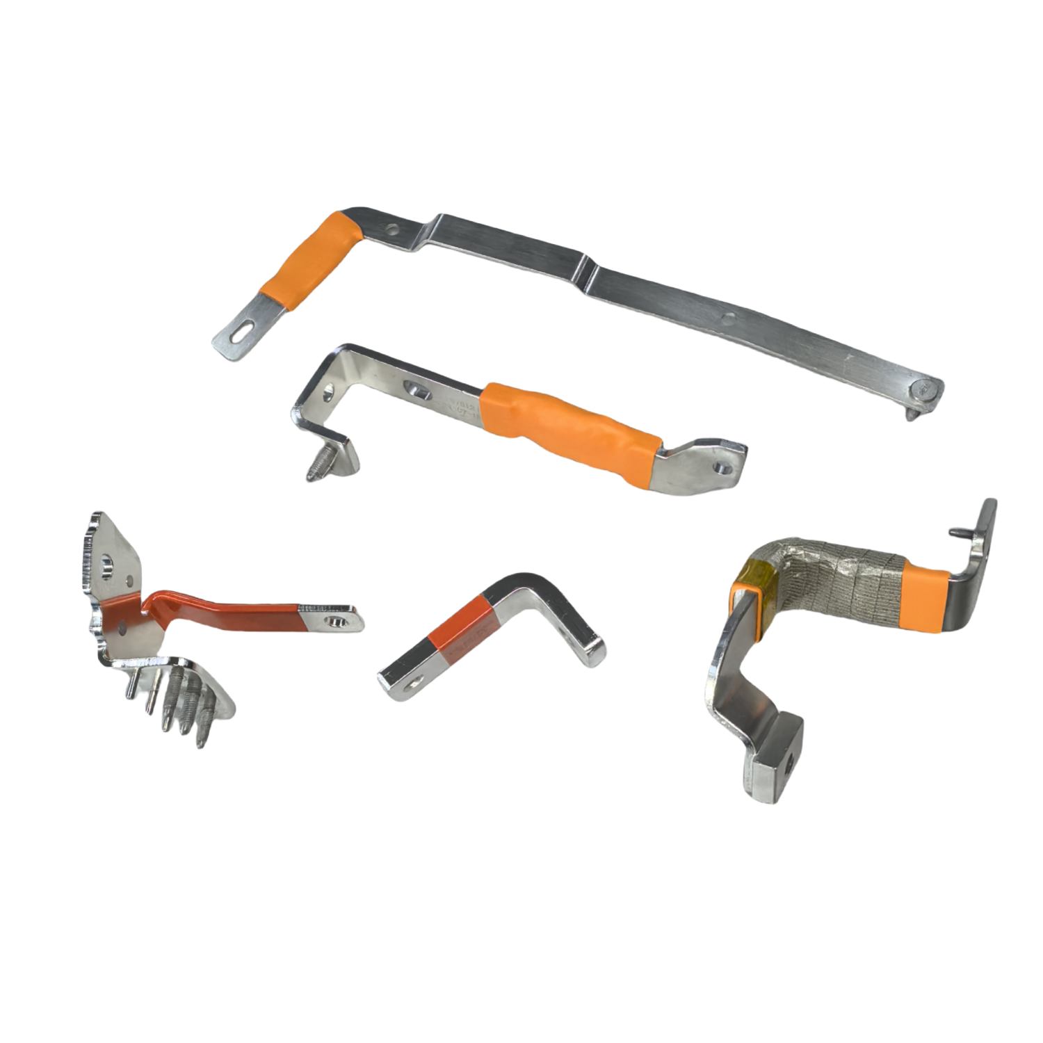
Consider the Skin Effect and Proximity Effects for AC Applications
In many designs only DC or low frequency AC is considered, in which the current is evenly distributed across the busbar cross section. At higher frequencies or with larger conductor sizes, however, the skin effect causes current to flow closer to the surface, reducing the effective cross sectional area available for conduction. This increases AC resistance and reduces the effective current-carrying capacity. For a copper busbar, the skin depth is approximately 8.5 mm at 60 Hz. If a busbar is thicker than twice the skin depth, the inner portion of the conductor contributes little to current conduction. The answer is to ensure that multiple thinner bars are used in parallel or to use laminated bars. The current-carrying capacity can be further lowered by proximity effect, which is caused by current being redistributed by magnetic fields in neighbouring conductors. In power distribution or inverter applications, Kinto helps customers understand how these effects impact AC busbars and recommends laminated busbar configurations that maximize current ratings while minimizing AC losses.
Apply Correction Factors for Shape Enclosure and Mounting Method
Heat dissipation is highly dependent on the physical configuration of the busbar and its mounting method. A flat busbar mounted vertically generally dissipates heat more effectively than one mounted horizontally due to improved natural convection. Busbar shape, conductor spacing, and surface area also influence heat transfer characteristics.
An open-air busbar benefits from unrestricted cooling, whereas the same busbar installed inside a sealed enclosure may experience a significant reduction in its current-carrying capacity due to limited heat dissipation. Likewise, multiple busbars installed close together generate mutual heating, which further reduces allowable current.
Standard correction factors published by IEC, IEEE, or manufacturer guidelines should be applied according to the installation configuration. Factors such as enclosure type, conductor spacing, airflow, and mounting orientation should all be considered when determining the final current rating.
At Kinto, our engineering team applies these correction principles during every custom busbar design to ensure that the calculated current-carrying capacity accurately reflects real operating conditions after installation.